It started innocently enough; I needed the traditional holiday radio project. The year before it had been the renovation of a R390A receiver, and the year before that was the cosmetic and electrical restoration of a T-368 transmitter. Despite my recent move to Portland, Maine this year was no different; I was keeping my eye out for a radio project to occupy my free time over the holidays.
The chance came right before Thanksgiving, when a 75A4 receiver popped up on eBay. (Say what you want about eBay, and I myself have mixed feeling on the subject, but the service does drag up a great deal of gear that would otherwise never see the light of day.) Debuting in 1955, the Collins 75A4 is arguably one of the finest vacuum tube receivers ever produced and is still highly sought after. This particular A4 was from the estate of a silent key, and had clearly been sitting unused for a long time. I never did learn his name or call, but I am almost certain I know what caused him to pass to the great beyond…in a word, nicotine. The A4 arrived safe and sound, but covered in a thick layer of yellow nicotine. Odd as it may sound, the nicotine’s effects on radios seem very much the opposite of its effects on humans. Indeed it seems to serve a purpose like Cosmoline, coating and protecting the finish for decades. Later in the article I will address my method to clean off this material, but let’s take a closer look at the A4.
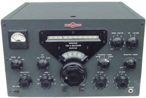
Collins 75A4
For a receiver now over 47 years old, the A4 seemed to be in remarkably good shape. It had the traditional scuff marks on the panel edges where the thin layer of paint had, in spots, worn away, but overall it looked quite nice. The 4:1 spinner knob in place, the pass band tuning knob was original, no extra holes were found in the chassis or cabinet, overall it was showing promise. A quick check under the “hood” showed the stock 3:1 mechanical filter in place, but mysteriously the 6AL5 noise limiter tube seemed to be missing. I checked the packing material, searching for the missing tube; it was nowhere to be found. As a glance at the schematic told me that the tube needed to be in place for the receiver to operate, my concern began to grow.
Normally my procedure before I begin work on any gear is to get a baseline of operations; use the unit, verify what works and what does not work and make copious notes for later reference. Never one to be shy with a screwdriver, the 6AL5 tube mystery and the frayed line cord offered me an excuse to take off the bottom cover, and I quickly removed the dozen or so screws that secured it.
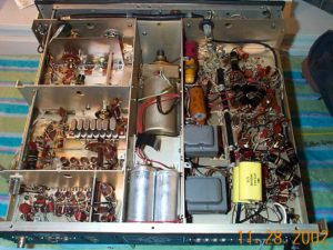
My first view of the 75A4 after removing the bottom cover. In the center rear of the chassis you can see the three electrolytic caps the previous owner had used to replace the multi-section electric cap that had failed. Note the large yellow caps on the right side that had been tied into the AVC line.
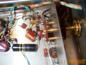
A close up of the mod on the 2nd mixer stage showing the resistor string. Note the dozen resistors used to replace just one resistor! You can just see the large scorch mark near the tube socket.
The first thing to catch my attention was the string of no less than a dozen resistors connected in both series and parallel up on the 2nd mixer tube. Someone had gone to a great deal of trouble to make up that configuration, and I wanted to know why. It seems that at some point in the life of this radio, the repairman had lacked the proper resistor and instead installed a string of a dozen resistors to reach the correct resistance and power rating! Not only did the 2nd mixer show signs of modification, but the 6AQ5 audio tube had a similar set of resistors attached as well. A dark scorch mark on the chassis near the 2nd mixer tube socket completed the picture.
As I looked around inside the unit I began to realize the scope of my undertaking. In radios that have been out of service for some time, it is common to experience failure of large electrolytic caps and my find was no exception. At some point, a well intentioned repairman had bypassed C94, a three section electrolytic, with three large discrete electrolytic caps mounted under the chassis. Not a bad repair, but certainly not appealing from a cosmetic standpoint. I further noted many of the carbon composition resistors had been replaced with metal films throughout the unit, and a large set of .47mfd caps tied to the AVC line.
Initially I thought I would simply replace the dreaded “black beauty” capacitors, but the mods, combined with the sloppy soldering job, melted wire ends; cold solder joints and poor lead dress told me that this was not a weekend project.
I should mention here that I am somewhat new to the vintage radio scene, first licensed in 1995; I just started getting my feet wet in the hot cathode emitter department only a few years back with an old military R-390A receiver and T-368 transmitter. During the R390A and T-3 work I had replaced many capacitors and resistors, but never on this scale. My first thought was to compare the radio in front of me with the schematic; however this is more problematic that it sounds. With a complex radio like the A4, the previous owners various mods and my lack of familiarly with the unit made this a very time consuming task. Ideally I would have another A4 to place side by side for a visual check, but that was not an option at this point. It was far simpler to look for the messy repair work. Fortunately, or perhaps unfortunately for the radio, the previous service had been carried out with an implement just shy of a blowtorch. The melted wire ends, excess solder blobs, and outright scorch marks on the chassis were simple to spot. I methodically made a written list of the various mods, component replacements, and questionable repair work, it was a daunting project.
The first order of business was to establish why someone did what they did to the radio. Allow me a few minutes on the soapbox here. I am sure that most of you, and I am guilty of this as well, have made personal modifications to gear. Nothing wrong with that, indeed the hobby was in many ways built on just that. However, one thing we should keep in mind is that in many ways we are just custodians of this equipment. I am certain that when the Collins people built this A4 they had no idea that it would be still in use nearly half a century later. Nor when the first ham did his repair or mod work on “my” 75A4 did he really think some guy in Portland, Maine in the year 2002 would be repairing it. No, at that time he knew what he was doing, it was his radio, and that was all that mattered. He never thought of documenting his handiwork, nor did his successors after him. Yet how many times do we find a radio missing the manuals, paperwork and other documents? Or worse yet, a nice clean boatanchor that someone has drilled a hole in the front panel to install some sort of convenience item, be it a pilot light, switch, headphone jack? Sure it’s your radio now, but what happens in 10, 20 or 50 years? I realize that until recently most of the vintage gear had fallen out of favor, and repairs were usually carried out in the most cost effective manner. But please keep this in mind the next time you feel tempted to save a few bucks on a part, or install that extra toggle switch; make it reversible and document your work. Had the previous owners done just that, my task would have been a simple one. We owe it to future hams to treasure and protect this gear, for their will never be another new 75A4.
So now I was faced with the somewhat daunting task of understanding what had been done to the radio, and if necessary, reversing it. But where does one find information on mods that may have been done nearly 50 year ago? Good question and I was about to find out the answer. The first place I checked was QST magazine articles from the 1950s and 60s. I have the QST collection from 1915 to 1964 on CD-ROM, which is a wonderful reference tool, but found little that matched up to my radios mods.
While looking on the QST CDs, I also posted a message about my problem to the Collins Collector’s Association (“CCA”) email reflector. Now, if you don’t know about the fine folks on the CCA email reflector, I need to tell you. My initial request brought me a number of responses, all interesting and informative. I learned that the mods in question were well known, even recently documented in Electric Radio. I received several offers from fellow hams to send schematics, mod sheets, and copies of articles. One gentleman even sent me a bag of silver mica capacitors to replace what has become known as the 75A4 “7 Deadly Caps” list, more about this list later. At first I was tempted to leave the mods in place, but the quality of the workmanship and mixed reviews on the effects of the mods soon convinced me to restore the radio back to stock. I wanted to make this radio look as stock as possible, so I needed to see how the components were originally placed in the modified areas. Another A4 to compare to side by side would be ideal, but my other A4 was in storage. A message to the CCA reflector asking about this brought a number of digital photos of the inside of the radio, particularly in the area of the 2nd mixer. It was then a straightforward process to remove the mod and install the correct parts.
Wiping my brow after that one, I undertook replacement of the multi-section electrolytic cap, and the “7 Deadly Caps” mentioned earlier. It was a simple matter to install the silver micas used in the interstage coupling, and the “black beauties” were quickly replaced with orange drop caps. I took particular care to use insulated tubing on the cap leads, keeping lead dress and workmanship to Collins standards. Only later did I discover that I had made a big goof when replacing the “black beauties”. I had used the incorrect value of caps. At some point I had read that these caps were .01mfd, but in actuality they were .1mfd. A lesson learned, verify the value of each and every component you are replacing. So once again out came the soldering iron, and the process repeated itself, albeit a bit quicker this time.
A close-up of the dreaded “black beauty” capacitors. These paper caps are a known failure point in older gear and should always be replaced during service, even if they test good.
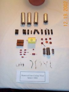
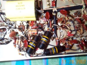
Components I removed from the A4. Note the long resistor strings, electrolytic caps and large number of “black beauty” caps.
With the caps out of the way, my attention turned to making this fine radio play acceptably with double sideband AM. A handy feature on the A4 is its ability to choose one of three internal mechanical filters. With the recent debut of SSB, Collins offered a number of filters for the A4, from the 500cycle CW filter to the 6KC AM variant. The stock A4 is equipped with a 3.1KC mechanical filter. The 3.1 filter is a compromise in many respects, too wide for CW, just marginal on SSB, and really too narrow for full fidelity AM reception. Collins suggests that AM can be tuned in with the 3.1KC filter if one selects either the upper or lower sideband, but I wanted true double sideband AM reception and this required the 6KC filter. The options for finding the desired 6KC filter are now few, look for a “vintage” now nearly 50 year old filter, or purchase a new one. I have to suspect that anything “mechanical” must have some degradation after 50 years of service, so I opted for the new choice, a fresh Dave Curry Longwave Filter from Electric Radio. As the audio was later to prove, this was both an excellent choice and value.
The last step in this effort was to address the cosmetic condition of the receiver. Cleaning a 50 year old radio is not an easy task. One wants to do a through job and yet not damage the paintwork or disturb the silk screened lettering on the front panel and chassis. Based on the collective input of others and my own trial and error, I have developed a comprehensive cleaning process that really seems to bring this old gear back to life. The cabinet was the first item to be addressed. The black crackle finish, tainted with nicotine, was treated to a liberal coating of “Go-Jo” hand cleaner. If you use this cleaner, be certain to get the type without pumice. During cleaning, it never fails to amaze me how much dirt and grime can be found hiding in black crackle paintwork. With its textured surface, the “hills” and “valleys” these finishes have a Velcro-like hold on the dirt and dust. Once the “Go-Jo” cleaner was rinsed off, carrying with it yellow streams of pungent nicotine, I treated the freshly cleaned paint to a light overspray of Wurth “Cockpit Cleaner”, a product originally intended for use on auto interiors. With the exterior looking like new, it was time to turn my attention to the inside. Fortunately this A4 had a very clean chassis, and all that was necessary was a through cleaning with Windex, followed by a light wipe down with WD-40 to prevent corrosion. A few evenings of work and the dust and debris from nearly half a century were gone, and the old radio looked like the day it came off the assembly line.
With the cabinet and chassis fresh and shiny, the moment of truth was now at hand. How would my countless hours of handiwork, the numerous fresh capacitors, resistors, and fancy new mechanical filter all work? Making certain the correct fuse was installed, just in case, I cautiously turned the 75A4’s power switch on, watching for telltale signs of smoke and the dreaded frying noise that accompanies a component giving up the ghost. To my delight, and perhaps astonishment, the tube filaments began to glow and a soft hum shortly emanated from the speaker, just as it should. Encouraged, I connected my test antenna; a 5 foot length of wire lying on the test bench, to the receiver’s antenna terminals. The moment of truth was at hand as I reached out and turned the band switch down to 160 meters. On 160 I knew I could just catch the top of the AM broadcast band, and hoped to snag my favorite “big band” station, 1490 WBCI. I slowly turned the tuning knob down toward the bottom of the band. The dial calibration was not quite right, but after some tweaking and tuning the melodious sounds of Nat King Cole’s “Unforgettable” emanated from the A4’s speaker, perhaps for first time in decades.
For me, there are few things that can compare to bringing back to life a radio that has been sitting dead for 10, 15 or 20 years. Repairing an old radio is really a never ending project, and in the coming weeks I discovered and quickly repaired other faults; a tube here, a resistor there, a potentiometer that crackled when turning. But for me, it is these little tweaks and fixes that I find most gratifying. Sure, I still have to do the dial calibration and the RF and IF alignments, but for right now, I think I’ll just sit back and listen to some music from my 50 year old time machine.
73 Bruce W1UJR
Recent Comments