Intro
This was written back in the last 1990s when I lived near Buffalo, NY, in a suburb that had zero lot lines, and little space for antennas. A vacant field in back of my home became the antenna field for my station.
– Bruce W1UJR
As some of you may know, I am an advocate for wire antennas, and have been experimenting with horizontal loop antennas for HF work. I am currently running a 160-meter full wave loop that is suspended about 30-40 feet off the ground. Although the feedline for my loop is currently coax, in future installations I am considering the use of balanced, or open wire feedline for reasons of low loss, which may be the topic of a future article.
One caveat that I should mention before I start. The majority of my operating, and hence my observations, is on the lower bands, typically 160 through 40 meters. At these frequencies, the use of a yagi antenna is often impractical due to size constraints. If you do operate on 20 meters and up, you may find a yagi a better choice than the loop for its gain and directivity. That being said, what holds true for a loop at 160 meters, also holds true at 10 meters, so even those who operate on the “high bands” should find something of interest here.
Wire Loop Antena
The loop antenna has a long and distinguished history, but is often overlooked in light of the current focus on dipoles. However, loops do have some rather significant advantages over a dipole. Since the design of a loop is typically a circle or square form, the need for a long straight run of wire used by a dipole is diminished. A loop is quite forgiving, and perfect symmetry is not essential. It is necessary only to hang it in the configuration providing the greatest enclosed area. As such a loop can be strung up in unusual places and still perform well. Treetop suspension is ideal, but you’ll be surprised how well it works just lying on the roof where nobody sees it. Unlike a dipole that must be center fed, the loop can be feed at any point, allowing a most flexible feedline arrangement.
A loop is an efficient broadband radiator, even when low to the ground. The majority of the amateur bands are harmonically related, typically the 1st harmonic. This is where the loop really shines, as a loop is easily tuned to resonance on all even harmonics of its fundamental frequency. A dipole by contrast is easily tuned to resonance only on its odd harmonics. A loop starts out with 1.2 dB of gain over a dipole on its fundamental frequency, and gains are even higher if the antenna is less than a quarter wave off the ground because that is where the dipole efficiency plummets. For example, in my location my loop is quite close to the ground, only about 30-40 feet up at the highest point. Nevertheless, the antenna both tunes, and transmits just fine.
A loop’s gain over a resonant dipole increases with the increasing frequency of operation, so when used on its harmonics, a loop’s signal advantage over a dipole likewise increases. For a horizontal loop, that’s not the end of the good news, because as frequency rises, radiation angle drops lower and lower, producing increasing DX results that can rival a complex multi-element beam mounted on a 100-ft tower.
The venerable loop is easy for your tuner to match, even when fed with coax. The feedpoint impedance of a loop never gets as high or low as with an antenna that has free ends. Even a 40-meter loop can offer full 80- 10-meter coverage. My 160-meter loop allows me to both receive and transmit from the 160-meter band to 10 meters. Signal reception is also quite good with a loop for a number of reasons. As it is a terminated antenna, it is much less susceptible to atmospheric and man-made noise. As the majority of man-made noise is vertically polarized, the horizontal polarized loop can reduce electrostatic noise as much as 26db when compared to dipoles or verticals, so it is great for noisy RF areas.
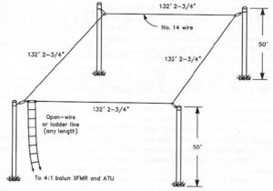
The theoretical feedpoint impedance for a full wave loop antenna is approximately 100 ohms, but this does change, and is dependent upon antenna height above ground, near-by structures, and ground conductivity. When used with a 2:1 balun this presents a good match to the typical 50-ohm coax. Due to the low height above ground of my loop, I used a 4:1 balun which seems to offer a wider tuning range (lower Q). With the use of a transmatch (antenna tuner) I am now able to use my loop from 160 to 10 meters.
Loops can be either a 1/2 or full wavelength long. The formula for a full wave loop antenna is as follows: Length (feet) = 1005/fMHz. For example, a loop for the frequency of 3.800 MHz would be calculated as follows: 1005/3.8 = 264 feet. You can now divide 264 by 4 to obtain the length of each of the four legs of the loop. 264/4 = 66 feet each leg.
So next time you need a new antenna installation, consider the time-honored loop. Simple and inexpensive to homebrew, you can put the money you saved toward something really important…like a trip to this years Dayton Hamvention!
-Bruce KG2IC
Recent Comments