April 24, 2011 – Elecraft KX-1 Build #2523 Now Finished, About To Start Another KX-1 Build
Just finished up the KX-1 build for another ham, I did have a problem last weekend during the initial build of this KX-1. Turns out that X-1, a crystal installed on one of the early stages was bad, it would work intermittently, the LED display coming on and off, discovered during testing, fortunately before getting too far into the build. Spoke with Gary at Elecraft, he was good enough to send out the parts I needed, along with another KX-1 build order. Installed the new X-1, all worked just fine. As per my standard procedure with all of my builds, I made notes in the manual about this, and also recorded the various voltages and resistance measurements during the testing phases.
Was delighted to use my Elecraft Mini-Modules during the testing and final alignment. Nice and compact, the Mini Modules sure bear dragging out the old and heavy! HP-8640 signal generator. Working very nicely now, was just copying CW on 40 meters, I am most happy with the rig. I usually like to operate it for a few days before sending back to the owner, just to test and tweak anything of concern.
April 18, 2011 – Elecraft P3 Panadaptor Build #1254
A fun build taking just over 1 hour, the P3 is a stand-alone DSP spectral/waterfall display unit that’s a perfect match for the K3. It has a built-in, high-contrast color display (LCD), point and click QSY tuning and better plug and play integration with the K3 than is possible with PC-based panadapters. P3 features include 2 to 200 kHz of span, signal averaging, peak hold, adjustable gain and adjustable reference level. It also includes a buffered IF pass-through for support of additional IF processing.
April 17, 2011 – Elecraft Active Audio Filter Build
The Elecraft AF1 is a versatile audio filter that can be used with any receiver or transceiver. It can improve intelligibility of CW, phone, or data signals, and is especially well suited to radios that have inadequate I.F. or audio filtering. A rotary switch on the unit allows you to select a low-pass characteristic with adjustable upper frequency roll-off, or a narrow bandpass characteristic. The bandpass filter offers two levels of selectivity, and its center frequency may be tuned from about 350 Hz to about 950 Hz. The low-pass filter is active during bandpass operation, allowing you to further control the upper frequency response. The output amplifier drives low impedance phones or a small loudspeaker. Power can be supplied via either an on-board 9-V battery or an external supply. An LED indicates power on/off status.
April 15, 2011 – Elecraft BL2 HF Balun Build
Highly-efficient balun can handle up to 250 watts and can handle 1:1 and 4:1 ratios via an on board switch. It is very small (just 1.5 x 3″) and lightweight, making it an excellent choice for both home and field use. It uses a special winding technique to reduce losses and extend the useful range, resulting in an SWR of less than 1.2:1 from 500 kHz to 55 MHz (200-ohm load). It includes rugged screw terminals for the balanced output as well as ground, and can be used in a variety of matching applications.
April 15, 2011 – Elecraft KX-1 Transceiver Build
Stage 1 complete.
April 10, 2011 – Here’s A Fun Vintage Radio Site – The RetroTechnologist
Here is a fun blog I’ve recently rediscovered, W9KIZ’s vintage radio blog, appropriately titled “RetroTechnologist”, also subtitled “I Commute From 1937”. If you enjoy old radios, and old technologies, you’ll find it a fascinating read at www.retrotechnologist.blogspot.com.
April 10, 2011 – Starting Another Elecraft KX-1 Transceiver Kit
Starting yet another KX-1 kit for a brother ham, always enjoy building these little rigs, the KX-1 packs an amazing amount of performance in a little package. Waiting for the pre-wound torrid coils to arrive, I’ve wound my share and now appreciate the pre-wound type, would rather save my eyes for reading!
April 9, 2011 – Building and Installing The Retro Helper For The Retro 75
Another homerun from Small Wonder Labs, the “Retro Helper” allows the Retro 75 transceiver to use the receive VFO as the transmitting VFO. No longer are you “rock bound” on two xtals, you can tune and transmit on the same range as receive. My rig covers 3835 to 3886 MHz, allowing some fairly good operating real estate.
The kit build is very straightforward, and if you’ve already built the Retro 75, you’ll find the Retro Helper a real breeze, took me about 2 hours, and that was being extra fussy about lead dress, solder connection quality, etc. The Helper board installs on the rear panel of the Retro 75 enclosure, using predrilled holes, and requires just 4 leads for connection to the Retro 75 main board. You can find the Retro 75 and the Retro Helper at the Small Wonder Labs website www.smallwonderlabs.com.
April 9, 2011 – Collins 75A-1 Alignment and Service Inspection
It had been some time since the old girl has been on the bench, dating back to my 2006 restoration.
Thought I’d take another crack at aligning the IF as I was not certain it was spot on. The original crystal in
the crystal filter was slightly off it’s target frequency of 500 Kc, so a quick align of the fixed and variable IF
brought all back into spec. The trusty HP 8640 signal generator was the ideal tool here, and I found I was
able to peak up the IF just a tad. The rest of the alignment was spot on from 5 years ago, a testimony
to the solid design and construction of the Collins gear.
April 9, 2011 – Radio Dust Covers – W1UJR Seal Of Approval!
Have been adding some dust covers to the station, got tired of using old bed sheets and blankets, which
although inexpensive, add their own dust to the items they are protecting.
Have been very pleased with the great work of Stand Clewett at www.radiodustcovers.com.
I can give a two thumbs up report for Stan for he has been excellent to work with, prompt on shipping,
and quite reasonable on cost. He responds well to custom requests, and is willing to explain the procedures,
can fabricate custom cover for vintage as well as modern gear.
April 3, 2011 – When Good Transformers Go Bad – BC-348 Receiver
I love the BC-348, it was my first tube receiver as a young shortwave listener, so I was understandably delighted to find another some years back. This orphan from World War II has always had a place in my radio collection. Generally, once recapped, the sets are quite trouble-free, and make nice workbench or chair side monitoring receivers. So I guess it’s only fitting that something might fail, after all, 70+ years is a long time to go without a problem. So it was that the neat little homebrew power supply inside my pristine BC-348 gave up the ghost this morning, seems the power transformer had a bit of a meltdown. Not sure what was more painful, the part failure, or the horrific smell that seemed filled the ham shack for the day, yikes! A good lesson, never leave tube gear on, no matter how reliable it has been in the past! A few hours, a new transformer, and some time for clean up and this fine old rig will be back in service.
March 19, 2011 – Elecraft K2 – Adding 60 Meters and RS-232 Control Board – KIO2 and K60XV Modules
Full computer control of the K2 is possible with the KIO2 installed, the KIO2 provides true RS-232 levels.
The system is compatible with most contesting and logging software, including some Mac based programs.
The KIO2 Programmer’s Reference provides extensive information for those writing custom K2 control programs.
Inside a fully optioned out Elecraft K2 – You can see the KIO2 installed, note the cable and two circuit board on the front and rear panels, the large gray colored wire is the data connection. Removing the right side of the K2 make it much easier to install the connectors for the RF, Power, Speaker and Data. Inside the Elecraft K2 transceiver, most modules are removed for service access.
Bottom view of the K2, with the front bottom cover removed for installation of the K60XV coaxial cable. Bottom view of the K2, with the front bottom cover removed for installation of the K60XV coaxial cable.
Front KI02 Board during build. Front KI02 Board during build, fully populated.
March 12, 2011 – Elecraft K3 – Adding The K144XV Internal 2 Meter Module
With the Elecraft K144XV internal 2 meter module installed, the K3 makes another leap forward in versatility.
The K144XV covers the full 144-148 MHz U.S. allocation, sp weak-signal CW/SSB work is possible, as well as
access 2-m repeaters. The receiver has excellent sensitivity and dynamic range. The maximum transmit power
output is 8-10 W in all modes, with diode switching for silent, relay-free T/R. Best of all, it fits right inside
the K3!
February 22, 2011 – Scope Testing Modulation On the Retro 75 Transceiver
Found that modulation was only possible to 60-70% before distortion occurs.
Measuring set up used – Retro 75 transceiver built by W1UJR, Elecraft DL1 Wideband Dummy Load,
Elecraft CP1 Directional Coupler, Elecraft 2T-gen 2-Tone Test Oscillator, and Elecraft W1
140W Computing Wattmeter and SWR Bridge for initial set up. All test equipment built
by W1UJR from Elecraft kits.
Found power output about 2.5 watts with an unmodulated carrier, does rises to about 4 watts at 60-70% modulation.
Waveforms were recorded on Tektronix THS720A Digital Oscilloscope.
AM Modulation Measured on W1UJR Retro 75 Transceiver
Ideal measured waveform – 100% modulation
Elecraft DL1 Dummy Load Elecraft CP1 Directional Coupler
Elecraft 2T-gen 2-Tone Test Oscillator Elecraft W1 SWR and Power Meter
January 30, 2011 – Building The Small Wonder Labs Retro 75 AM Transceiver
Been as busy as a beaver over the last few weeks with radio kits, and have more coming this week! As from Elecraft, I’ve also enjoyed kit from the good folks at Small Wonder Labs, www.smallwonderlabs.com, building a number of their kits over the years. Recently Small Wonder Labs came out with a simple, QRP power AM transceiver kit, called the “Retro 75”. I had looked at the kit many times, but always had other projects, so I finally ordered it a few weeks back.
Last night I started the Retro 75 build, was up to 4:30AM, lost track of time and really was enjoyed the project. I finished up the details this afternoon, and I estimate that it took me about 12 hours of total time. One could do it in less time, but I wanted to enjoy the process, and the moment it ceased being fun, I stopped and took a break. I also spent some additional time to make sure the solder connections and lead dress looked just right. In fact, I initially ran the wiring for the control and jack leads above the chassis, but it looked a tad too cluttered for my taste. Wanting to really enjoyed and be pleased with the project, I redid the wiring, and ran it under the PC board. The efforts were worth it, as the rig played the first time out. I did find one wiring error during my pre-power up testing, I had reversed the T/R and Power leads, easy to do as they are next to each other on the board, and I was working under the board rather than on top. During the alignment stage, the set was hearing shortwave stations with just my finger as an antenna, and even the two variable indictors, T1 and T2 did not require much tweaking, both were just about spot on.
Some notes about my build, as I mentioned earlier and per the suggestion of Dave K1SWL, I ran my control and jack leads under the PC board, rather that on top, it makes for a cleaner looking build, used heat shrink tubing to keep the lead dress neat. The 3A/B/C capacitor selection confused me at first, it was not until I read later in the manual that I fully understood that those different values were used to set the turning range. Since the instructions are rather free form, I chose to build using component types, rather than board areas, this seemed to speed things up as I could sort the values before install. So the caps went first, then the resistors, inductors, etc. The system worked pretty well, and I used the component listing as check sheet, marking off each part on install. I’d ideally like to see some sort of plug in header for the wiring, so the board could be removed for service, inspection, but this is by no means a necessity, also a plug in xtal holder would be nice, so could sway out xtals, guess I can implement pretty easily, and both options would only add to the very reasonable cost for the kit.
I bought the optional enclosure, glad I did, works well with the rig, With that said, I would really love to have the anodized aluminum case like the ones offered with the Small Wonder Lab DSW series back in the late 1990s, but that is something which I am working on. Power levels, for AM carrier, varied between 3-4 watts without modulation, right on spec, as you can see by the Elecraft power meter photo. RX side seems to work well, nice and sensitive, pleased about that, looks like a real bargain for the money. In summary, the Retro 75 is one very fine kit, a great weekend project, quite well designed, well priced, looks like Dave has hit another homerun with this one!
Retro 75 parts sorted out. Beginning the Retro 75 build, note Elecraft K3 in background for entertainment.
Retro 75 on schematic. Retro 75 built and installed in case, all wires routed under board for clean lead dress and appearance.
Close in view of the Retro 75 board, coils wound and board build by W1UJR Overview of the transceiver, sitting on top of build manual for size reference.
RF testing of the Retro 75, Elecraft W1 SWR/Power meter in the background, note 3-4 watt reading on the W1 LED display. Retro 75 ready for on air testing, fine little RX was well.
January 30, 2011 – Balance In All Things
The Amateur’s Code, written by Paul Seagal W9EEA in 1928,
is an excellent reminder of what amateur radio is really all about.
January 29, 2011 – Building The Elecraft N-Gen Wideband Noise Generator Kit
Why does one need a device which generates a wideband noise on the HF bands? Well, its not as malicious as you might think, in fact its really quite useful for aligning filters, doing a quick check of receiver operation, etc. I found this a simple but fun kit, takes less than an hour to build, and perfect addition to the test workbench, which also includes the Elecraft W1 140W Computing Wattmeter and SWR Bridge, the XG2 Three Band Receiver Test Oscillator / S-Meter Calibrator, and now the XG2 Three Band Receiver Test Oscillator / S-Meter Calibrator.
The folks at Elecraft tell it best, so here is the description of the unit from their website:
The Elecraft N-gen is a wideband noise source that is useful for a variety of receiver alignment tasks. It can be used in conjunction with a software program such as Spectrogram to align IF filters in the K2 or in other receivers. It can also be used to align the RF stages in Elecraft XV Transverters or other HF, VHF, and UHF equipment. Note: The N-gen does not generate repetitive pulse noise, so it cannot be used to test pulse-type I.F. noise blankers such as the Elecraft KNB1 or KNB2.
Specifications
Power Requirement: 9V battery or external 12 to 15 volts DC
Current Consumption: approximately 25 ma.
Excess noise output: approximately 35 dB
Bandwidth: within 3 dB from 100 kHz to 500 MHz
N-Gen Noise Generator Kit Assembled N-Gen undergoing testing
Using the N-Gen to check a transceiver, connected to antenna input, signal is displayed on S meter Note the S meter reading from the N-Gen, perfect for testing filter alignment, etc.
January 23, 2011 – Elecraft K3 – Adding The KPA3 Internal 100 W Upgrade for K3/10
The 100 Watt PA module simply converts the QRP version into a standard QRO HF radio, QRP is still possible when the power level is reduced, thus making the K3 able to do double-duty as a QRP/QRO radio. In fact, the front panel display automatically switches between the 1-10 watt and the 1-100 watt scales when the K3 switches from the low power IPA to the higher power unit, nice feature Elecraft!
January 23, 2011 – Elecraft K3 – Adding The13 Kilocycle Filter
Great for listening to HiFi AM amateur and short wave broadcast stations, really opens things up from the stock 6 Kc filter!
January 23, 2011 – Elecraft K3 – Adding The K3XVA Board
January 16, 2011 – Elecraft K3 – First Contact – Antique Wireless Association AM Net
My first QSO with the new rig was today on the Antique Wireless Association Sunday AM PM Net on 3837, altogether fitting that the rig should make its maiden voyage both on AM and on the AWA Net! A most interesting juxtaposition, 1940s antique gear meets the latest and greatest of the 21st century! Thanks to Bill K1BF and Dave KA2J for listening very hard for my little 2.5 watt QRP signal.
2011 Elecraft K3 1947 Collins 30K
January 16, 2011 – Elecraft K3 Build Finished – Works Wonderfully!
Finished the K3 today, spent a good part of the day doing the final tweaking, listening to 75 meter AM group as I type this. All told it took me 5, maybe 6 days, I spent mostly a few hours each evening, choosing to take my time to assemble, test and verify the kit. Sure that I could have done it one or two sittings, but I choose to savor the experience, it really was fun, of course one fellow did it in 7 minutes…www.youtube.com/watch?v=DfUMZcwtIyw. Of course that’s a time lapse video, done over several days, but still one gets the idea.
General Impressions
I had a ball building the K3, its like an erector set for adults, all bolt together – no solder. I’ve got a K2 to build for another fellow, suspect that is going to be a little more of a drudge after breezing through this. Part of what makes the experience special is the support of the Elecraft community, like the AM Fone site, there are dozens upon dozens of knowledgeable folks more than willing to help out with anything question or glitch you may encounter, that sense of community is invaluable. Best part – NO TOROIDS TO WIND – I am way over that, was fun for the first two, maybe three kits, but no more. I did not add the 100 watt module, happy to run with the QRP 10/12 watt LPA, that seems to be the focus for me in 2011, less is more.
January 16, 2011 – Elecraft K3 – Final Building Tips and Suggestions
K3 Utility Software – KSUB Adaptor – A Small Glitch
First, kudos to Elecraft for supplying software for the Mac, so little ham software is written for the Apple side of things that it was a pleasant surprise to see that both a PC and Mac version of the K3 Utility software on the Elecraft website. The K3 Utility is used to set up and test various rig parameters on the K3 transceiver, and while not required, is very handy to use. With that said, I did have a bit of a challenge with the software. Like most new computers, my Apple Macbook Air does not have a serial post, just two USB ports. The K3 uses a serial port, necessitating the use of a USB to 9 Pin Serial cable, Elecraft sells such a cable, known as a KUSB. Despite repeated efforts, I could not get the K3 software to find the adaptor cable on the Macbook. I tried various software drivers, searched the internet and Elecraft email archives with no success.
Finally, I made a quick post to the Elecraft reflector, and within 10 minutes of my post Bill K1GQ nailed it. Turns out that the drivers from the Elecraft site are NOT correct for the FTDI chip set which is used on the newer KUSB cable. I downloaded the correct driver from the site Bill suggested, and things just worked! Just 100% delighted how quickly and well the K3 Utility works. The site for the FTDI chip is located at http://www.ftdichip.com/Drivers/VCP.htm Even more delighted with the prompt and accurate help provided by K1GQ on the problem, hope this saves someone else from this challenge. So, if you’ve having an issue with the KUSB on the Mac, use the Mac System Profiler to determine which chipset your USB to Serial Adaptor is using, then make sure you download the right driver.
Crystal Filters – Double Check/Double Take
I found the otherwise excellent Elecraft assembly manual a tad confusing, at least to me, on the arrangement of the xtal filters. I had chosen the 8 pole xtal Inrad filters for the K3, the layout is as follows: 250 KC, 450 KC, 2.8 KC, 6.0 KC. Those with a sharp eye will note that I initially had the filters installed in the incorrect order in K3 because I misunderstood the manual. A reading of the operations manual made things much clearer to me, and I quickly reinstalled all of the filters from the widest bandwidth to the most narrow. The new order is: Filter 1 is blank for future installation of the FM filter, then I set it up the following filters from widest to most narrow, 6 KC in slot 2 for AM, then the 2.8 KC filter for general use, followed by the 450 and 250 KC filters for CW use in slots 4 and 5 respectively.
Using A Icom Microphone on the K3 – General Info
I have a number of Icom rigs here, and more than a few spare mics laying about. I decided to use a Icom SM-8 with the K3. The SM-8 has a bit of retro look about it, nice contrast to the K3, and the electret condenser type mic element gives clear tone over a wide variety of voice levels. On the bottom of the mic base there is one control for tone. Designed to be used on two different rigs, there are separate level adjustments for input A and input B. The mic cables terminate to a standard ICOM 8 pin mic plug.
The use of a Icom mic requires a few simple changes as Elecraft has wired the microphone jack on the K3 to match the Kenwood wiring scheme. Unlike the K2, the user can not readily change this scheme, so the changes have to occur inside the microphone or cable plug. The pin out information on both the Icom and Elecraft is below, again, hope this helps someone else. You have two settings on the K3 which need to be enabled to use with the Icom microphone, the Bias voltage, and the Mic Gain. For my station I used the high mic gain setting, and also used the bias voltage, seems to work just fine. The Icom memory channel or freq changing is implemented differently that Kenwood, Icom does this by pulling down a control voltage with a 470 ohm resistor. Adding the functionality of the UP and Down buttons will require some additional work, I have not implemented that, but may do so at a later date.
How To Wire The Icom SM-8 Microphone To The K3
To implement the simple microphone cable mod, use the table below.
For simplicity sake here is a simple list of how I switched the cable leads:
1) Remove the two screws on the female mic cable clamp, then remove the one small screw holding the mic
connector into the shell.
2) Now twist and remove the mic connector from the shell, slide back the clear plastic sleeve to access the small pins on the back of the connector.
3) Using a fine tipped soldering iron, carefully unsolder Pins 2, 5 and 6 on the Icom mic plug, be sure to note which color wire went to each pin, see chart below if in question – note, your cable colors may not match mine, so best to make notes.
4) Solder the wire removed from Pin 2 to Pin 6 (bias voltage).
5) Solder the wire removed from 5 to Pin 2 (PTT)
6) Solder the wire removed from Pin 6 to Pin 7 (ground to ground).
7) For the VFO or memory channel up functions, skip this step now, I’ll have more data in a future post.
8) Reassemble the mic connector back into the shell.
9) Using the K3 Config menu set up the Mic Gain and turn on the Bias voltage, see the K3 manual for info.
10) Set the mic gain pot to a setting which sounds good in your on-air test and you should be all set.
Icom Pin Connection Wire
Color Elecraft
Pin Connection
1 Mic Input White 1 Mic Input
2 + 8 VDC Black 2 PTT
3 Up/Down Blue 3 Down
4 Squelch N/C 4 Up
5 PTT Red 5 Function
6 Ground Brown 6 Bias
7 Mic Ground Shield 7 Ground
8 Audio Out N/C 8 Ground
January 16, 2011 – First 2011 New England AM QRP Net Debuts
Summary – New England AM QRP Net for 2011. First, it was all good, people actually showed up and got on the air, so 10 points to the fellows for that. Second, most stations were reasonable copy, despite power levels and QRM from 3885.
Following stations were in the net:
W1VZR – Pete
KA5WHO – Dale
W1VTP – Al
W1TAV – Steve
KF1Z – Bruce
W1FRM – Guy
WA1LGQ – Larry
WA1KPD – Carl
W1UJR – Bruce
January 12, 2011 – Elecraft K3 Build Day 2
Ready for resistance checks and power up tomorrow evening!
Basic Configuration
I kept my kit pretty simple, the options order is below.
– K3/10 K3 10W Xcvr. (Modular Kit)
– KAT3 K3 ATU (Modular Kit)
– KBPF3 K3 Gen. Cov. RX Module
– KDVR3 K3 Dig. Voice Recorder
– KFL3A-2.8_2.7 2.8 for 2.7 kHz swap
– KFL3A-250 250 Hz, 8 pole filter
– KFL3A-400 400 Hz, 8 pole filter
– KFL3A-6K 6 kHz, 8 pole filter
January 11, 2011 – Building the Elecraft K3 – Here We Go Again!
When Nancy and I were visiting my folks back in New York state over the Christmas holidays, I had the opportunity to drop off a Henry amp to its new owner, Bill N2BC, his photo below. Of course a shack tour was in order, and Bill has a very nice hamshack indeed, equipped with the latest and greatest in Elecraft gear, the K3. Bill’s K3 really got me thinking…a Elecraft K3 would be a very fun project for the New Year…and I am always on the lookout for a new project…
Over the past few years I’ve built a number of Elecraft kits for myself and for others, I’m on the Elecraft builders list, it is always a blast, makes the long Maine winters go quickly! The KX-1, K1, K2, and miscellaneous Elecraft mini kits, but never the K3, considered the top of the Elecraft mountain. One listen to Bill’s K3 and I was hooked, needless to say, the order, with Bill’s guidance and suggestions, went in shortly after I returned to Maine.
The K3 is different that other Elecraft offerings, it is a “no solder” kit, the builder basically assembles pre-tested and assembled modules…still, building is building and I was excited to get back on the bench. The kit arrived today, and I was in the barn this very evening, a cup of green tea at hand, sorting parts out into muffin trays, inventorying components, the old National HRO short wave set going in the background, a most wonderful Maine winter evening. Serial number 5068 is under way!
The Elecraft K3 – Stock Photos
Blame it on Bill N2BC – A Very FB OM
Starting My Build – Had To Add Another Workbench To The Line Up!
January 8, 2011 – AM QRP – 2 1/2 Watts AM -Retro 75 QSO Today – 1940 meets 2010
Interesting QSO today with a fellow running 2 1/2 watts AM! A most intriguing juxtaposition, 1940s era Collins 30K running 250 watts to a 2010 Small Wonder Labs Retro 75 running 2.5 watts, believe it was even the maiden voyage of his Retro transceiver. The Small Wonder Labs rig can be found here –>> smallwonderlabs.com/Retro-75.htm
I called CQ about 1800 UTC on 3880 Kc was delighted to get a call back from Jerry AA1OF using the Retro 75 rig. Audio was a tad distorted until he switched over to another mic, but once that was done he sounded great from the speaker of the 75A1, every bit as copiable as the other stations running mid to high power. It is quite amazing little power you really do need when conditions are right…and they are usually right most early to mid afternoons. And I believe his antenna was partially made from speaker wire?
Remained very easy copy for an hour before I had to sign. Enjoyed a very good roundtable of other fellows, some who could and could not hear him, KC2JXX, W1VTP, W1FRM, KC2TAU. That’s four states – ME, NH, NY, MA, even voice from Vermont BHV called in.
Early afternoons, the band is usually very quiet and few stations are on, but it is generally open through the northeast, so don’t hesitate to call even if things sound dead, you just never never know who is listening!
January 1, 2011 – We Begin Our 5th Year Of Bruce’s Bench – Welcome To The New Year!
Bruce’s Bench – the name is rather unassuming, the concept quite simple. The idea was to, via the internet, take folks out to my workshop, turn on the lights and show them the various projects scattered about on my workbench. Originally intended as but a simple way to update friends from out of town as to what was percolating on my service bench, this series has grown into one of the more popular pages on my humble site.
When I first started out back in 2007, I had envisioned this serial as a simple photo documentary, but as time went on, it has slowly developed into a journal of sorts, and perhaps, if you will excuse the expression, a showcase of talents, interests, ideas, and yes, even misadventures. As we begin our fifth year of Bruce’s Bench, my hope is that you have enjoyed reading along as much as I have enjoyed creating it, for the serial has allowed me to connect with all sorts of interesting folks, acquire some rather unique radio gear, document a small bit of radio history, and along the way make some wonderful friends. Kind folks have shared their own stories with me after reading an article in the series, or have greeted me at ham fests and shared just how much they enjoyed a posting, photo or project…that really makes it all worthwhile.
I’m ready now for a new year in amateur radio, with more projects to undertake, more radios to add to the collection, more challenges to chase down, and perhaps most importantly, more time to spend with friends! My best for the New Year to one and all…and if I may be so bold as to borrow a phrase from Dickens’ most wonderful tale, “A Christmas Carol”…God bless us, every one! May we all take the lesson of Ebenezer Scrooge to heart, and begin the new year refreshed and renewed with the joy of redemption.
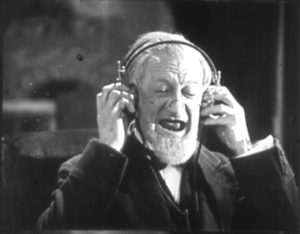
Old Buzzard Bruce Tunes In A New Signal In 2011…
Recent Comments