Such a rig really deserved to be placed in, and kept in first class condition, so I began to consider my restoration strategy. Over the years the original black wrinkle finish had been redone, but the lower parts of the chassis, and undersides were showing rust. The finish was also soft, and the coil sets sitting on top had stuck to the finish, leaving circular impressions.
So first on the list was the paintwork, and last year, when I restored the Gross replica that John had built for Marshall W2ER, I made inquiries about the refinishing of vintage black wrinkle paint. Traditional black wrinkle paint, once so ubiquitous with gear from the 1920-30s, has all but disappeared. It seemed the only real alternative offering both durability, and a reasonably authentic appearance, would be powder coating.
Powder coating is a modern, and quite durable method to finish sheet metal. During the powder coating process, the sheet metal is electro-statically charged so the aerosol powdered paint will adhere to it, and is then baked at high temperatures. The result is a most resilient finish, and a close match to the old black wrinkle finishes. Numerous inquiries were made, until the trail pointed me to the door of Wayne Spring W6IRD in California. Wayne did a stellar job with the W1FPZ rig, so I naturally trusted the Gross CB-25 to him. Wayne is quite a gentleman, and most graciously said, “Just send it out”. With the refinishing tasked out, I began the long process of documentation and disassembly of the transmitter.
-
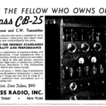
- Gross CB-25 Transmitter

-
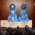
- Won for restoration of the W1FPZ tx
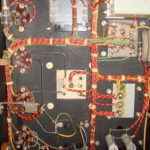
Since I planned a complete tear down and restoration, it was critical to properly document the layout of the rig for reassembly. Herein was the largest challenge I encountered during the entire project.
The Process
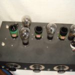
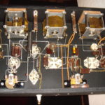
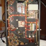
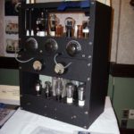
The CB-25 transmitter really consists of two separate decks, an RF and combined Modulator and Power Supply. So armed with my trusty camera, I carefully photographed the RF and Power Supply decks from every angle, to assure that I could properly disassemble, and then reassemble the units when the sheet metal came back from Wayne’s shop. This idea worked like a charm, and soon I had a better record of the transmitter than if I had only a schematic, for the photos showed not only where various wires were connected, but also the lead dress and layout.
One odd challenge I did encounter was with the insulation of the meter leads. Like much vintage equipment of the era, this unit used meters that were secured to the panel with their 3/8” mounting studs. Since plate voltage for the lower stages, as well as the output tubes, was present on these studs, it was imperative they be insulated from the metal panel. The original rubber insulator bushings were far too cracked and dry-rotted to be trusted with B+ voltage. My trusty local hardware store came to the rescue. I found the perfect solution, nylon bushings with a thin shoulder to insulate the meter studs from the metal of the panel. After a little attention with a file, the bushings were a perfect fit, and the meter panel looked quite authentic.
Details, Details, Details
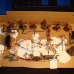
So it was with some trepidation that I made the big decision, and pulled apart the entire power supply, lettering and tagging each lead with paper labels. I used the digital photos I had taken earlier to label each component, assigning names such as “T1” and “R3” right on the photo. In this way, with the part names now noted on the paper tags, I could unsolder multiple component leads and still readily identify each connection point.
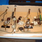
The RF deck, unencumbered by transformers and chokes whose leads extended through the panel, was a much simpler process to disassemble. After several hours of work, I was left with a pile of parts, dozens and dozens of Ziploc baggies affixed with labels such as “RF Deck Knobs”, “Power Supply Hardware”, and “Gross Dial sets”. With the set of panels were heading west to Wayne to work his magic on, in the meantime, the pile of parts lay on the workbench, reminding me during each visit to the ham shack of the project which lay before me.
At the same time I sent off the panels, I also placed an order with the good folks at McMaster-Carr for an assortment of stainless steel fasteners. I was quite impressed with McMaster-Carr’s selection, and I was able to find some period looking hardware. Most early radio gear uses slotted rather than more modern Phillips heads, often with a countersunk design. I learned a trick some time back about using the countersunk washers under the front panel screws. You’ll often see these washers used on old Collins gear, with a small cork insert underneath to prevent marring of the front panel. Those cork gaskets are long gone, but you can also buy nylon countersunk washers as well, and they will fit right inside the stainless steel ones. By using this method you provide an authentic look, slotted head screws, metal countersunk washers, with the black nylon washer inside protecting the front panel. In a few weeks, the sheet metal panels came back from Wayne, looking every bit as nice as the first set he did. I was tempted to jump into the project right away, but I really wanted to make this the best that I could, so I waited until the weekend.
While the rig was torn down, I took the time to inspect and clean each component, and repaint some of the transformers and capacitors. This was the ideal time to carry out cleaning and refinishing, and the results were most rewarding. Assembly of the unit took a little over 1 month, working 2-3 hours of time each session.
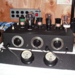
With the power supply and RF decks now assembled, I took time to check the power supply voltages before mounting the rig in the sheet metal cabinet. As Gross had fabricated the interconnect wiring harness for use in the rack; it was too short to run the transmitter with the decks side by side for bench testing. Sensing light at the end of the tunnel, I eagerly fabricated a longer cable for testing. All went off just fine, and soon I had my “dummy load” light bulb glowing brightly. Listening to the signal note in my monitor receiver, it was clear the unit was operating just fine. Confident of my work, I installed both in the chassis for final testing.
Live To Air
On May 15, 2009, my 45hth birthday, the Gross CB-25 returned to the air. My initial testing consisted of using a 40-watt light bulb as a dummy load, as I peaked and dipped the various stages. Operation of the Gross rig is quite straightforward. To operate the transmitter, one turns on the small switch located on the left lower panel energizing the filament transformers. One then tunes each stage, working from right to left, starting with the oscillator and progressing to the buffer and final amplifiers. The two panel meters are plugged and unplugged, as each stage is set. When fully loaded, the CB-25 rig puts out a solid 20-25 watts of CW carrier, and is very stable.
With Thanks
In closing I’d like to thank my good friend Larry NE1S for his technical assistance, Wayne W6IRD for his masterful sheet metal work and powder coating, Tim W1GIG for sorting out John’s paperwork and forwarding over Gross materials, and finally my good friend John W1FPZ SK, who reminded me again of the true magic of radio.
73 Bruce W1UJR
September 2009
Woolwich, Maine
Recent Comments