*Circa August 13, 2005
Today in the middle of a FB QSO with K1MVP the plate blocking capacitor in my 32V crapped out.
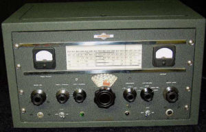
Collins 32V Transmitter
This was evidenced by an immediate loss of RF, a loud hum and the telltale pegged plate current meter. Even my trusty old buzzard RF indictor, a large neon bulb JS lashed onto to my balanced feedline terminals, showed no glowage, a very bad sign. When something like this happens out of the blue, a thousand thoughts run through your mind. Is it the final tube, did I inadvertently hit some knob, did the modulator transformer give up the ghost? I quickly unkeyed the transmitter thinking my antenna relay had stuck, as Dowkeys sometimes do. A check of the relay showed that all was intact and the fault must lie elsewhere. Switching between bands or from Fone to CW had no effect, still a pegged plate meter. I considered that something may have happened to my antenna or feedline, but transmitting into the dummy load brought the same result.
I should mention that this was my Elmer’s, W2UJR – now a Silent Key, former transmitter, so the thought of some major failure made my heart sink. When I obtained the unit from Dick’s estate, I had brought it back to life by replacing a stubborn failed screen bypass capacitor on the 4D32 final tube. Since that time it had run flawlessly, despite the somewhat troublesome reputation of the 32V series. The unit had followed me from Buffalo when I moved to Maine and had become my backup 75 meter transmitter at the office. Rumor had it that Dick only ran it on CW as he did not care for the lack of civility on 75 meter Fone.
Ironically I had just been on the telephone earlier in the day speaking to my friend and fellow Collins enthusiast, Bill K2LNU. Bill shared that, after he had spent countless hours working on them, he was now seriously considering selling some of his Collins 32V transmitters because they were such a project to service. With that cheery thought in mind it was out of the cabinet with the 110 lb transmitter, an exercise which had become an all too common event.
I say common as for most of the proceeding week I had been working on a new acquisition to the W1UJR hamshack. A exceptionally recalcitrant Collins 32V3 which displayed a most troubling linearity fault with the Permeability Tuned Oscillator (PTO). It was only after multiple attempts to diligently adjust the linearity, as specified in the service manual, each involving a trip in and then out of the cabinet, that I discovered that the linearity simply could not be restored to the 50 year old PTO. A returned call from Collins guru Howard Mills W3HM confirmed this and I was informed that some years back Dallas Langford had discovered that the ferrite compound used by Collins in the PTO changed its molecular structure with time. So it seems that unlike wine, ferrite does not improve with age, hence the PTO would no longer track properly. As the PTO was a relatively recent invention at the time, Collins had no way of knowing of this during the initial design of the 32V series. Indeed its doubtful they anticipated their handiwork would still be in used half a century later, so no provision was included in the PTO design to compensate for the ferrite change. Anyway, back to our story.
With my failed 32V on the bench I did a quick check of the mica capacitors used in the output loading network. In the 32V series these capacitors are always suspect and have a high failure rate, especially when used with non-resonant antennas. Still, each of the mica loading capacitors checked fine with the DVM, not a fault among them. This meant that I had to dig digger, or in other words this going to take some time. The next step was to remove the plate connector from the top of 4D32 final tube and see what happened with the plate current. I suspected that the tube had perhaps experienced some catastrophic internal failure. Yet again I was stymied, the tube tested out fine, and I still found pegged plate current with the tube plate capacitor removed.
Curiosity got the better of me and I then removed the tube completely from the socket and applied plate current, same result, pegged plate meter. Since the final tube was entirely out of circuit and I still had excessive plate current, as a quick test I removed the coax connector from the rear of the transmitter, Eureka, plate current was now at zero. I now knew that a fault existed in the output network, but where? The 32V series is one of the most tightly packed and difficult transmitters which I have worked on. Despite Collins excellent manuals and documentation, service on these units requires both a great deal of patience and dexterity.
At that very moment I was on the air with Larry NE1S, yes, multitasking. Carrying out a QSO and checking for plate voltage may not be the wisest course if one wants to enjoy a long life. However, in this case it had a payoff. I described the fault to him and explained my findings. Larry confidently asserted that, given my symptoms, it could only be one thing, a failed plate blocking capacitor. With the transmitter keyed, I checked for plate voltage at the RF connector, 890 volts! Sure enough, the plate blocking capacitor was allowing full plate voltage to show up on the output of the antenna! Instead of blocking the plate DC, it was in fact conducting it! Not exactly a safe thing, in fact it was downright dangerous. If I had not had the tuner in line, full plate voltage would be applied to the antenna feedline and leads, ready to zap some unsuspecting passerby. So with that discovery, the next logical step was to unsolder one lead of the plate blocking capacitor. A resistance check showed that my plate blocking capacitor was now a resistor, reading about 23 ohms on the trusty Fluke meter.
The capacitor in question is one of the older square mica capacitors that you see in transmitter output networks, with two mounting holes and solder tabs on the end. This capacitor in particular was rated at 2500 working volts and 5000 test with a value of .001. It displayed no visual sign of failure, no burn marks, case swelling or discoloration. For all intents it looked like a good capacitor, in fact it looked new.
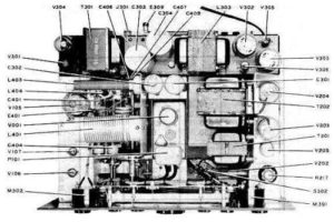
Collins 32V Transmitter
As I mentioned before, the 32Vs are a real challenge to service.
If you have ever had the joy of replacing the plate blocking capacitor in a 32V, heck if you have done any service at all on these 32V series rigs at all, you know what a project this was. A quick check of the spare parts bin yielded the needed capacitor, those $5 coffee cans of parts dug out from under tables at hamfests sure do pay off.
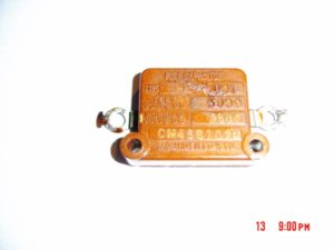
Failed Collins 32V Plate Blocking Cap
However, finding the capacitor was the simple part. It took me nearly 90 minutes to remove two screws and solder connections on the failed capacitor and install the replacement. The Collins design team had conveniently located the plate blocking capacitor about 3/8 of an inch from a large wound loading coil. Since access to the Phillips head screws which retained the plate capacitor was simply not possible with a screwdriver, I had to settle for turning each screw 1/8 of a turn at a time with a pair of needle nose pliers. So to say things are tight inside the 32V is a major understatement.
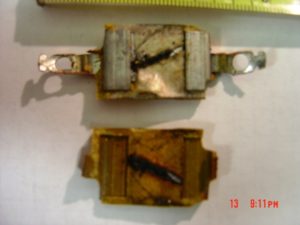
Failed Collins 32V Plate Blocking Cap
Curiosity and abundant spare time got the better of me and I decided to open the defective capacitor up for an examination. After all, things that zorch out are often pretty interesting to look at. By examining the exterior of the capacitor I could see a manufacturing molding line around the upper edge of the case.
Using a bench grinder, I carefully ground away the edges of the case, removing the bonding joint of the upper and lower sections. A small chisel was then used to split the case halves open for a visual inspection. It was quickly apparent what had failed on the capacitor. The center section of the mica had been carbonized from end to end, essentially creating a carbon composition resistor. No wonder at all that I measured 23 ohms of resistance across what was once a capacitor.
So, can those more knowledgeable than I, which is probably a good number of you out there, offer up an explanation why this occurred? Operating plate current was normal, perhaps a tad conservative before the failure as this is my Elmer�s former TX and I run her lightly.
Did the 50 years finally catch up with the capacitor, or did the Zorch Gods just decide it was time? Are there other causes for this? If so I’d like correct them so I don’t have to replace another.
Bruce W1UJR
Recent Comments