Intro
I’ve added this wonderful article, written some years back by John, to the site as it represents knowledge now largely lost, except by those few who still practice the art of home brewing pre-war gear.
By reading John’s work, and by carefully following his instructions and schematic, it should be possible for any licensed amateur to build and then operate one of these wonderful early transmitters. You can find more information about early gear at www.antiquewireless.org.
Should you undertake this adventure, be sure to participate in one of the many Antique Wireless Association Contests which feature such gear. You can view current and upcoming AWA Amateur Radio activities at www.antiquewireless.org/awa-events.html.
You can also click and download a copy of this work in PDF format –> W1FPZ – Thoughts On Push Pull TPTG Transmitter.
Enjoy, and I hope to hear you on the air!
73 Bruce W1UJR
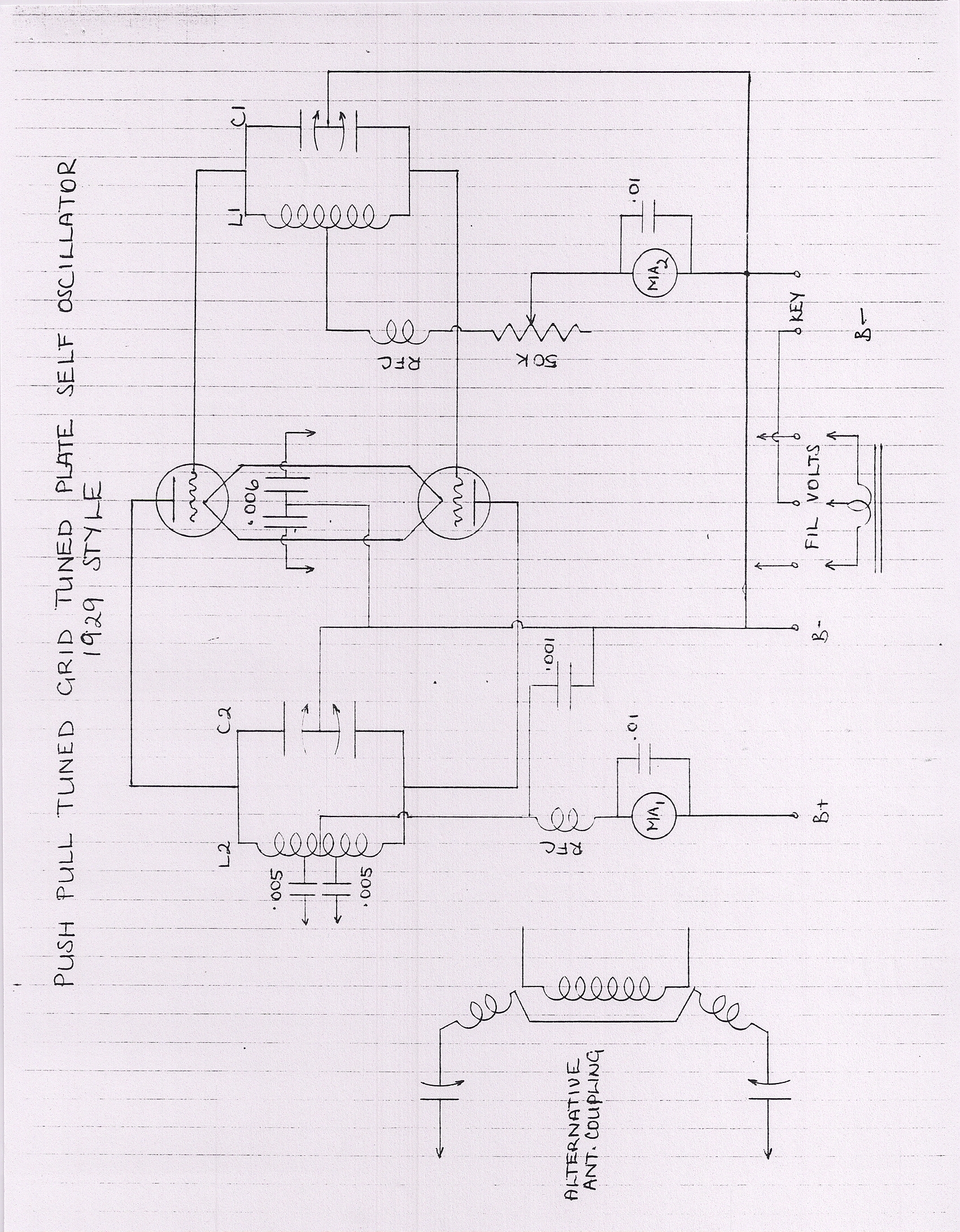
PUSH-PULL TUNED GRID TUNED PLATE SELF OSCILLATOR
1929 STYLE
By John Rollins W1FPZ SK
Early last fall Parker, WlYG, piqued my interest in 1929 type self-oscillators when he showed me an early article on building a push-pull oscillator. His stated intention was to build such an oscillator for the “1929 or earlier” AWA contest coming up in November.
Self oscillator circuits of the 1929 vintage come in several types, the best known of which is the single tube T.N.T., (tuned plate, untuned grid type). Other common ones are the Hartley, the single tuned plate, tuned grid, and the push-pull oscillators. The common tubes of the day were the type 45 and the type 210, and of course the type 852 – if one really wanted to generate some power.
Having never built a push-pull self oscillator, I proceeded to delve into the various aspects of the problem using a tuned plate – tuned grid circuit. The first attempts followed the conventional circuits shown in the 1930-1934 ARRL Handbooks using the type 45 or type 210 tubes. The results, while they may have met the amateur requirements of that era, left something to be desired in today’ s crowded band conditions. The chirps and the yoops were quite impressive. Obviously more research was needed on my part.
After several weeks of experimentation the end product has turned out to be quite satisfactory, and the result on the air is a surprisingly clean, stable D.C. note. I feel prompted to pass this information on to other members of the Antique Wireless Association in hopes that a few more push-pull oscillators will come on the air for either the November, or the February AWA contests.
The accompanying circuit is quite straight forward, and can be found in the 1930-1934 ARRL Handbooks, as well as several of the early QST magazines. Only some of the component details and operating parameters have been changed, in an attempt to improve the quality of the signal, as outlined below.
TUBES
In the early days, most of the low-powered oscillators utilized the type 45 or the type 210. Either type may be used here. The 210 is much more flexible in power output and may be driven up to about 30 watts with a good power supply. However, the 7.5V filament may require a little more flea market digging to produce the transformer. The type 45 uses the 2.5V filament transformer, which is generally easier to find. The comments in this article pertaining to tuning, loading, and voltages, are for the most part, applicable to either tube.
GRID CIRCUIT
Some of the early circuits utilized an untuned grid circuit. However, past experience has convinced me that a tuned grid provides much more flexibility, and ease of moving about the band.
The grid tank circuit utilizes a low-C capacitor. This is a departure from the early days which seemed to favor the high-G in the grid, as well as the plate circuits. A dual 100 pf capacitor works well and easy to tune, acting much like the band spread condenser in some receivers.
Finding authentic “period” dual stator condensers may take a little patience at the flea markets, but in the meantime a more “modern” thirties model, such as a Hammarlund dual stator receiving type, or a National TMS capacitor, will work nicely. In the transmitter illustrated in this article, I used a single stator National DX receiving capacitor of fine pedigree, and modified it to a low-C dual stator. This only requires making three additional insulated mounting blocks for separation of the two stator sections. The capacitor can then be disassembled and reassembled with three stator plates mounted on each frame end plate, attached through their respective insulating blocks. Three rotor plates for each section, properly spaced to mesh with the stators complete the job.
The beauty of using the National OX type capacitor is that the old National Type A vernier dial may be mounted directly to the capacitor frame, which greatly facilitates tuning.
The grid coil form is 1 inch in diameter and 3~ inches long. If you cannot find some old one inch, or so, Bakelite coil forms, a good substitute is 1 inch diameter DELRIN plastic rod, black, which may be bored out with a 3/4 inch drill. The result will look quite authentic. Banana plugs are mounted at each end of the form, and also one in the center. Finding the old green DSC wire may be a bit of a challenge, but as an alternative one can use 1126 nylon covered wire, and dye it green. This wire can be supplied by RADIOKIT. Three brown glazed standoff insulators with banana jacks complete the assembly.
The RF choke can be anything handy. One of the early, universal wound RF chokes would be authentic. A variable rheostat is recommended for the grid bias circuit. A 50K ohm wire wound rheostat is the best, but a 25K or 30K variable, with a fixed resistor in series to make up the total 50K, will do. Mount the rheostat on a piece of 1/8″ aluminum plate for rigidity.
A 0-20 or 0-30 milliammeter is strongly recommended in the grid circuit. This will allow you to adjust the grid current to about five to eight mils. Too high a grid current will encourage chirp in the oscillator.
PLATE CIRCUIT
A dual stator, 500 pf per section plate tuning condenser, may take some rummaging at the flea markets and/or some ingenuity. Fortunately there are several alternatives to the problem of acquisition. Fair Radio Sales sells a dual Cardwell capacitor, which has one section of 25-485 pf and 23-427 pf for the other. One of the stator plates in the higher cap section can be easily cut out with a hacksaw, making the two sections equal at 427-427 pf. A little more coil inductance will be required with this lower cap., see coil winding data. Occasionally the Old General Radio dual cap., of 500 pf per section, can be found. These are very good. Also the old Cardwell balanced rotor dual SOO turns up occasionally. I am sure there are other types of dual 500 caps.
If one has access to a small metal turning lathe, a very nice dual 500 pf variable can be made up from two National DX 500 single capacitors, see photo. A new rotor shaft will have to be turned, and also a spacer sleeve will have to be made to separate the two rotor plate sections. The shaft needs to be about 5 1/4 inches overall, and the spacer sleeve about 3/4 inch long. Four new tie rods will have to be made. These should be 4.4 inches long and made from ¼ inch dia. aluminum, or brass rod. These will need to be drilled and threaded at both ends for 6-32 machine screws. Each stator section is mounted on the respective front and back end plates through three insulating blocks. Again, a National Type A dial can be mounted directly onto the capacitor back plate. A number of the early circuits show a single ended plate tank circuit with a push-pull oscillator. Don’t even try it. The oscillator will chirp wildly.
The plate tank inductance may be made in several ways. To be authentic the coil should be wound of 1/4 inch copper tubing. A piece of 3 inch dia. PVC pipe or a heavy cardboard tube will work nicely as a mandrel. As an alternative to the copper tubing, a section of 3 inch dia. AIRDUX coil, 4 turns per inch will work nicely, see Coil Data. The finished coil should be mounted on three brown glazed beehive insulators.
Coupling to the antenna, or to an antenna tuner, may be accomplished by tapping directly off the coil, through blocking capacitors, or by the use of pickup coils on each end of the tank coil. Pickup coils seemed to be the most common method in those days. These coils were generally made of three or four, turns of 1/4 inch copper tubing, with one end of each coil fastened to a beehive insulator, so that the coils could be swung out to vary the degree of coupling. I chose to tap onto the tank coil. Two Sangamo micas, .005 or .006 pf seem to do the job. Twisted pair lamp cord can be used to tie to the antenna tuner.
A “proper” plate RF choke should be wound on a 1/2 inch dia. wooden dowel 3 1/2 inches long. A 3 inch winding of #26 or #28 DSC wire makes an effective choke. Again, if the green OSC wire cannot be found, the 1126 nylon covered wire, dyed green will make a close approximation.
CONSTRUCTION NOTES
Any type of “breadboard” may be used. Be sure to use rubber bumper feet on the underside corners. Make construction and wiring as rigid as possible.
Hand capacity effect is a “given” with these self oscillators, and it can make precise tuning troublesome. The hand capacity effect is in large part due to the hand disturbing the fields surrounding the two coils when you reach up to tune either capacitor. However, the effect can be greatly reduced in the grid tank circuit, which will help final frequency adjustment.
Mount the grid coil several inches (3 or 4) back from the front of the breadboard. Then mount the grid bias control, with its aluminum mounting plate at the front of the breadboard, and on center line with axis of the coil, see photo. When making the mounting plate for the rheostat, be a little generous with the dimensions of the plate. (3″ high, 2 1/2″ wide is a good compromise.) The plate will partially shield the field surrounding the coil from the hand. This will greatly reduce the frequency shift that occurs when the hand reaches up to adjust the bias control or the grid tuning capacitor.
The grid and plate milliammeters should be given some attention to rigidity in their mounts. Mounting posts can be made from 1/2 inch dia. aluminum rod. Four 2 inch long posts will be required. Drill and tap both ends of the rods to accept 8-32 machine screws. The rods, or posts are fastened to the breadboard with 8-32 screws from underneath the board.
Four pieces of aluminum 1/8″ thick x 5/8″ wide x 3 1/4″ long are used to make the two pairs of mounting brackets. Bend a right angle foot on one end of each piece, and drill a hole in each foot to accept an 8-32 screw. The opposite end of each piece should be drilled to accept the terminal bolt of the meter (1/4″ hole). Each piece is fastened through the foot to the tops of the posts with 8-32 screws. The pieces may be bent back if desired, to tip the meters slightly upwards. A meter is fastened on the two aluminum strips by bolting the 1/8″ strips directly onto the terminal bolts of the meter. This makes a fairly rigid mount. Electrical leads are connected at the base of both mounting posts.
POWER SUPPLY
A few notes on the power supply for the oscillator may be helpful. A good power supply will contribute greatly to a clean note from the oscillator. The transformer should have at least a 200 MA rating on the high voltage secondary, and should be capable of producing 400 to 500 volts DC for the 210 tube, and 350 to 400 volts for the 45 tube. A higher voltage and a light plate loading will contribute significantly to a chirp free signal. The filter choke should be rated for 150 to 200 MA with a low resistance. A heavy bleed across the DC output will help regulate the supply to the oscillator. A 15K ohm, 100 watt resistor is recommended. A light duty power supply will give poor regulation, and contribute to chirp in the oscillator.
TUNING
A grid dip meter is helpful in initial tuning of the oscillator, but a receiver can do the job. Using a GDM, set both the plate and grid tuning capacitors for the middle of the 80 meter band. Set the grid bias resistor at about 35K to 40K ohms to start, then switch the power on with the antenna circuit uncoupled to the tank. Key the oscillator, and if the grid and plate capacitors have been previously set with a GDM, the oscillator should show resonance, as evidenced by a low plate current reading, (about 10 mils).
Set your receiver on the frequency desired, and slowly vary the plate tuning. No doubt a number of spurious “birdies” will be heard, but when the fundamental is tuned, the receiver S meter will swing off scale. Then adjust the grid capacitor to show about five to eight mils of grid current.
The antenna may then be coupled to the oscillator plate tank. This will immediately move the signal off frequency. However, by alternating adjustments of the antenna tuner and grid capacitor one should be able to bring it back to the desired frequency. Load the oscillator to 25 to 50 mils, depending on the power desired, and adjust the grid capacitor to about 5 to 8 mils grid current. If a good DC note is not heard in the receiver, increase the capacitance of the grid tuning, and readjust the grid bias resistor to maintain the 5-8 mils grid current.
Loading may be increased as desired by the operator within limits of the regulation of the power supply. With a well regulated 500 volt supply, the plate circuit can be loaded to about 70 mils for a pair of 210 tubes before any chirp begins to appear. Loading can be adjusted at the antenna coupling system as needed to meet the “under 10 watts” requirement for the 1929 contest. A 400 volt power supply, with 20 to 24 mils loading, works nicely for this requirement.
Once the oscillator is fully adjusted on the desired frequency, you will find that you can easily move up or down frequency 10 kc – by varying the grid capacitor. The plate capacitor will not need to be touched. A wider frequency excursion will require resetting the plate tank, and the grid capacitor may have to be readjusted to maintain resonance.
Finally, I must acknowledge that all that I have written here is “old hat” to the real old-time hams in AWA, but it is hoped that this article will be of interest to those of us Johnny-come-latelies, 68 years and below! Good luck, and if I can be of help to anyone, please give me a call, or write.
COIL DATA
The coil data presented here only covers the 80 meter band, but if desired, the oscillator will work very nicely on 160 meters and 40 meters, with the proper plate and grid coils.
Grid Coil – 80 meters
1″ diameter coil form, 3 1/4″ long Bakelite, or other material. 56 turns close wound, center tapped #26 DSC, or equivalent. Note: If other parameters are used in making coil, or coils for other bands, adjust winding to let grid capacitor tune to resonance about 50% mesh.
Plate Coil – 80 meters
3″ diameter, 6″ long, 16 turns, center tapped 1/4″ copper tubing or AIRDUX 3 inch dia. 4 TPI 16 turns center tapped (use 18 turns AIRDUX with Cardwell dual 427 pf.)
PP OSC. COIL DATA
PLATE TANK GRID
160 M 3” DIA 36 T CT 1/2” DIA 65 X 65 T
6 TPI 6” LONG # 29 NYLON
80 M 3” DIA 20 T CT 1/2” DIA 24 X 24 T
4 TPI 6” LONG # 26 OSC.
40 M 2 1/2” DIA T CT 1/2” DIA 15 X 15 T
1/4” COPPER TUBING # 22 NYLON
6” LONG
20 M 2 1/2” DIA 8 T CT 1/2” DIA 7 X 7 T
6” LONG # 22 NYLON
TUNING INSTRUCTIONS FOR 1929 PUSH PULL OSCILLATOR
1. Turn power supply on 15 to 30 min before transmitting.
2. Set grid cap about 50 to 60% open.
3. Disconnect twisted pair at TX.
4. Depress key and while listening on RX tune plate capacitor very slowly. There will be a number of harmonic signals heard, but only the fundamental will swing the S meter full scale.
5. When the fundamental is found, adjust grid cap for best note and frequency.
ANTENNA TUNER
6. Set both caps about 50%. Taps on both coils should be about 15 turns.
7. Connect twisted pair to TX.
8. Depress key – you will find that signal frequency has shifted.
9. Tune right hand cap on Ant. tuner slowly until you hear sig. on RX.
10. Check grid current and vary grid bias resistor, if necessary, to read 4 to 8 MA grid current. Sig. will shift frequency.
11. Bring signal back to desired frequency on RX by adjusting right hand cap. on ant. tuner.
12. Load TX to Ant. by varying left hand cap.
To increase loading, decrease capacitance.
To decrease loading, increase capacitance
You should be able to load TX to 40-50 MA before any chirp appears.
13. Readjust right hand ant. cap to bring TX back on frequency.
Always adjust grid current to read 4 to 8 MA.
SUMMARY
Once the desired frequency is found by tuning the plate tank, this cap. can be left alone. All subsequent adjustments can be done with grid cap, grid bias and antenna tuner.
W1FPZ – Thoughts On Push Pull TPTG Transmitter
Recent Comments