While this is for the 101X, most it likely applies and hold true for any of the National moving coil products.
What had occurred to this unit, is that the plastic bushings had been brittle, loose and broken over the last 80 years, the coil became unusually binding when I attempted to move it. Concern that I might damage one of the unobtainable coil sets, or the contact fingers, let me to a solution. Since National is no more, I figured I could find a current product, and adapt that to the application. McMaster-Carr is an excellent source of such items, and small hardware, and a quick search of their online catalog found several possible candidates. Since the shipping was more than the $5 parts, I ordered two sets of the plastic and one set of the bronze bushings to try.
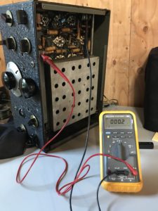
One thing I did have to satisfy myself on, was if the coil Assembly itself was a ground potential. Being insulted by the plastic bushings, I wasn’t sure if the coil housing was actually electrically insulated. Having another NC-101 on hand made it pretty straightforward work, I removed the bottom panel and using a ohm meter verified that there was continuity from ground to the coil assembly itself. I was glad to discover this, because it meant I could use bronze bushings without fear of grounding the sliding coil.
Step by Step Removal of the Sliding Coil Assembly
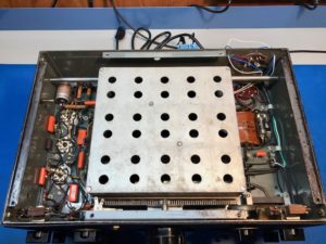
- The first step is to remove the bottom cover of the unit, this will expose the moving coil.
-
Then the cabinet needs to be removed, which necessitates removal of the knobs, and disconnecting the s meter.
-
The next step is the front rack and gear which moves the coil back-and-forth. You can actually start with this step if you want. There is a nut on the front panel it needs to be loosened and some hardware, including two insulator bushings, that attach a gear to the front panel. You’ll need to remove the top part of the sliding coil housing was necessitates removing six screws, so you can slide the gear up over the housing for removal. With that done, entire sliding coil assembly should lift free of the chassis.
-
With a cabinet removed on the rear the chassis there are two flat head screws which retain the shaft on which the coil rack slides. Removal of the screws may take some effort, they likely been in there for over a years, and you don’t want to strip them out. The use of an impact screwdriver with the proper size bit, would be recommended.
-
Once you have the screws loose on the sides, the rod will still be retained has there are two dimples in the chassis which fit into the countersunk ends of the rod. You’ll also note that there is a small braided ground cable, which is retained to the rod via a small machine screw and nut. Be sure to remove these, before attempting to remove the coil.
-
Once you have the braided cable loose, using a large screwdriver carefully pry out the shaft from the counter sunk ends. It will take some effort, but the shaft will finally pop free.
- With the the shaft now for free of the chassis, you can carefully pick the sliding coil rack out from the receiver. I would recommend putting the cover back on the top of the catacomb, just so no stress is put on the fragile coil forms while working with it on the bench.
- In regards to the bushings, you’ll likely find that the bushings size is slightly larger any opening in a moving coil assembly. You’ll need to do one of two things, either machine be opening in a coil assembly to a slightly larger diameter to except the bushings, or machine the bushings to a slightly smaller outside diameter, for a tight press fit into the coil assembly. Either choice is acceptable, since the original bushings lasted 80 years, it is unlikely that replacements will be required again, especially if the bronze style bushing as fitted.

Recent Comments